|

|
Navigation
 Contribution;Comment Contribution;Comment
 Interchangeable gear calculation Interchangeable gear calculation
Geometry of bevel gears
Worm and worm wheel
Donation to the site
If you use this site regularly and would like to help keep the site on the Internet, please consider donating a small sum to help pay for the hosting and bandwidth bill. There is no minimum donation, any sum is appreciated - click here to donate using  or simply send a PayPal donation to ninoslav.pacic@gmail.com. Thank you very much for your support! or simply send a PayPal donation to ninoslav.pacic@gmail.com. Thank you very much for your support!
News
Performance report
The further maintenance of this site is subject to the Interesse. Update on the 20-03-2013:
Gear quality tolerance zone to DIN3967; Axis distance ISO-Symbol js; Circular deviation; Angular alignment deviation.
|
Tips & Tricks
Internal Gear and Spur Gear:
- Number of teeth of the wheel with the sign '-' type
- The sign of the Profile shift coefficient of the wheel note
- Enter gear quality tolerance zone of the wheel to 'h'
|
|
|
|
|
|
Sizes of individual wheel and gears pairing - easy, fast and completely free!
Useful knowledge to the understanding: concepts and determinants for cylindrical gears
Data entry:
send for test given data, or
enter new values
- Pressure angle
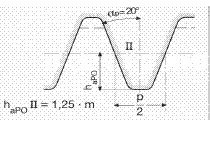
 The flanks of the reference profile, (DIN 867), include with the normal to the profile baseline the profile angle equal to the angle α. The reference profile of gear cutting tools is set according to DIN 3972.
- Profile shift factors x 1 and x 2 are given
The box for the axis distance leave blank; it is shown in the result.
If profile shift factors x 1 and x 2 and axis distance are given, predetermined profile shift factors are negligible as a result.
For the given axis distance program calculates x1 and x2 for lowest tooth root bending stress.
- The profile shift coefficient x 1 or x 2 and the axis are entered
the box other profile shift coefficient leave blank,
it is shown in the result
Note: The radially measured amount of displacement from the location affecting the reference circle,
Profile shift called, is charged off positive shift from wheel centre and negatively charged to shift against the wheel
centre (applies also with internal helical gear).
- Enter axis distance
Input fields of the profile shift factors leave blank, on the contrary the previous criterion is valid.
For the given axis distance program calculates x1 and x2 for lowest tooth root bending stress.
procedure for a new pair of gears:
- Enter the number of teeth, Helix angle, normal module
Leave blank input fields of the profile shift factors and the center distance; so-called "zero wheels" with the "zero distance"
- Examine the result:
A reasonable distance would be of (zero centres) to (zero - distance + normal module)
- enter in the draft approved center distance and "Submit input data"
- In the new result is calculated x1 and x2 for lowest tooth root bending stress
Sliding roll ratio VC/VR on the pinion tooth head shall be not greater than at the wheel tooth head; Sliding roll ratio VC/VR at the wheel tooth head shall not be greater than 3; (Sliding speed must be not greater than 3 times roll speed)!
An adaptation is possible with the change of Center distance.
For a stabilization of VC/VR sliding roll relation enter one using the "copy paste" of the corresponding profile addendum modification factors from the result as a new entry.
- Input data submit and examine the result
The result list offers the additional values of:
Transverse module; Pitch circle diameter; Tip diameter; Root diameter; Base circle diameter;
Upper & Lower tooth-thickn.deviation; Tooth thickness tolerance; Tooth thickness variation according to DIN3967; Tooth pitches;
Normal circular pitch; Circ.pitch (Trans.-); Transverse base pitch;
Transverse contact pitch; Face contact ratio; Number of replacement teeth; Span measurement;
Normal tooth thickn.; Circular deviation; Flank line angle deviation;
Sizes of external helical pairing: Tooth number ratio/Gear ratio/; Operating pitch diameter; Root diameter;
Operating pressure angle in the face section; Pressure path; Active profile length of the tooth head Head coverage level;
Transverse contact ratio; Total contact ratio; Backlash; Radial clearance; Sliding-roll ratio; / SPECIFIC SLIDING /;
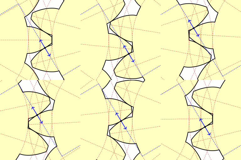
Meshing on the screen.
Top of page
|
|


 Interchangeable gear calculation
 The flanks of the reference profile, (DIN 867), include with the normal to the profile baseline the profile angle equal to the angle α. The reference profile of gear cutting tools is set according to DIN 3972.